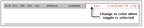
When any of the toggle buttons on the Toggle Bar are turned on, they will display red letters on a white background; they are turned off when they display black letters on a gray background. Switch or toggle between the off and on state by pressing the button.
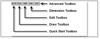
Toolbox Toggles
All the DynaScape Design toolboxes are controlled using the buttons shown below. Clicking the DRW button for instance will open the Draw [Creation] toolbox.
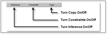
Command Toggles
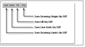
Line and Drawing Environment Toggles
Inference Settings
Drafting with DynaScape is made easier by using a small but powerful tool called an Inference Engine. As the name suggests, this tool allows the program to infer specific reference points found on existing objects in a drawing. By referencing these locations, such as endpoints and midpoints of lines, or origins and quadrants of circles, you can create accurate arrangements of entities, without having to enter precise location coordinates. By turning the Inference toggle on, tools and functions that can use inference will automatically snap to available inference points that it finds as your cursor gets close to them. The controls that govern Inference can be seen (or edited) by right-clicking on the Inference toggle and selecting Properties or by opening the Inference Settings panel (Environment | Inference Settings).
See Chapter 4 Menus, Settings and Controls for more detailed information about inference and how to use them.
Constraints
The Constraint button, “Select the active constraint mode”, assists various commands by defining a particular path, angle, or direction. This tool effectively duplicates the function of a T-Square and triangles used when drafting on a drafting board. For example, with DynaScape Design, you can set constraints to horizontal so that a line is drawn only horizontally, without your having to set an angle in a Modifier. Similarly, you could use constraints to force entities to be moved or copied along a set path or in a fixed direction.
Selecting the Constraint button in the Toggle Bar displays the menu in the diagram below.

There are four types of constraints:
1. Ortho (snaps to 90 degree increments).
2. Horizontal (snaps to 0 degrees, or 180 degrees).
3. Vertical (snaps to 90 degrees, or 270 degrees).
4. Polar (snaps to whatever angle is entered under Set Polar).
Angles for the Polar option can be set by selecting Set Polar from the displayed list. By default, the Polar constraint is set to 45 degrees in DynaScape Design prototype drawings.
Set Constraints (make Constraints active) by clicking the Constraint button in the Toggle Bar and choosing an option from the menu. To turn off constraints, select the Constraint button and choose “None” from the displayed list.