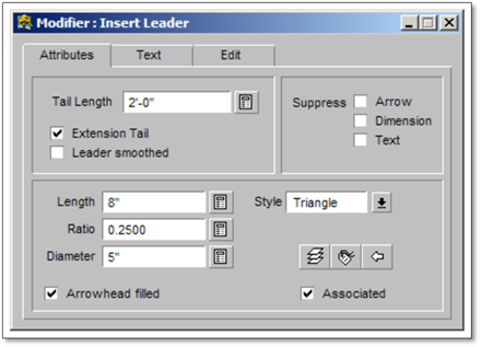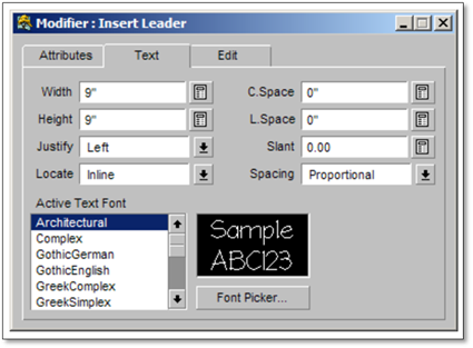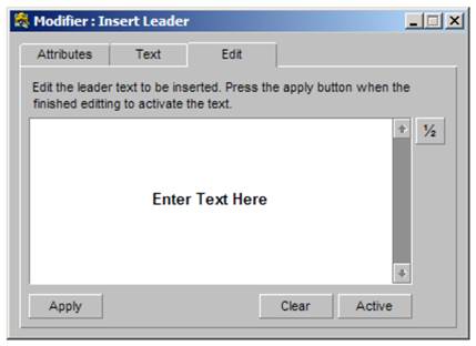
The text with a leader tool is made up of three component tabs:
1. Attributes.
2. Text.
3. Edit.
The Attributes Tab
This tab contains the setting for the leader and the arrow style. DynaScape defaults these settings so they are consistent with other leader text (softscape labels, dimensions, etc.) that may be used in the drawing. In this tab you can change the shape and size of the arrowhead, the length of the extension tail, etc. to suit your needs, but remember that these settings will only remain effective until this panel is closed and will not affect any other label, new or existing, on the plan.

If you wish to change these setting so they are there each time you open the tool, read the section at the end of this chapter called Editing Global Text Settings.
The Text Tab
This tab is where the text settings are changed including the font being used and the size of the font. Again, there are default settings applied here to match other label settings elsewhere in the program and any changes made will only affect the current text and will be abandoned when the panel is closed.

The Edit Tab
This tab is where the text that is to be placed on the drawing is entered. Only one line of text can be entered each time.

Using the Insert Text Attached to a Leader Tool:
1. Click on the Design_Mode. The Design_Mode will set the active layer to Text Labels (the recommended layer for text) and turn the constraints on to Polar (needed to control leader lines). You can set this manually as well.
2. Click on the tool (shown above) to open the modifier.
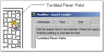
3. Generally, you should not need to change the default settings for both the Attributes and Text areas but work solely in the Edit area. Enter in the text you wish to apply.
4. Click the Apply button.
5. Click on the drawing where you want the arrow to point.
6. Click at the next location you wish the leader line to extend. You have the ability to add ‘elbows’ (bends) to the label as needed.
7. Once the label is in the final location, right-click to drop the label onto the drawing.
