In order to draw property lines that contain arcs you will need to know the length, the bearings and the radius of the arcs. Since bearings cannot be entered into the modifier boxes of the radius tool, you must first draw a temporary straight line using the length and bearings specified on the lot plan. All lot plans with bearings for curved line will have the following information to determine the angle, length and radius:
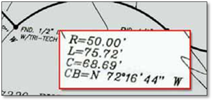
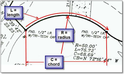
‘R’ represents the Radius of the curved line (needed to get the correct curve)
‘L’ represents the Length of the curved line (not needed but useful to check accuracy)
‘C’ represents the Chord of the line, the distance between the ends of the curves (needed to get the length correct)
‘CB’ represents the Bearing angle of the Chord (needed to get the angle correct)
There are two formats to enter bearing measurements and they are dependent on the way the numbers are displayed on the property survey:
Bearings: Showing degrees, minutes and seconds and a direction e.g., N43°32’09”W
•If the degrees are over 90 you must use the DMS format
DMS: Showing degrees, minutes and seconds only (no direction) e.g., 169°54’06”
•This format does not allow the use of a direction (N, S, E or W)
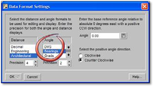
The first step to begin this process is to change the format in which you enter your data:
1. Under Angle, choose the Bearings or DMS option and click OK.
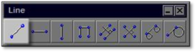
2. Click on the Draw a line tool to open the modifier.
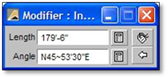
3. In the Length box enter the length of the Chord (C) from the survey.
4. In the angle box enter the bearing angle of the Chord (CB) from your survey in this format:
Using the Bearings Format:
N0~0ʹ0ʺW (the ʹ~ʹ represents the degree symbol)
 Note:
Note:
If the degrees are over 90 you must us the DMS format.
Note:
 The
letter ‘d’ can be used in place of the ‘~’ symbol
The
letter ‘d’ can be used in place of the ‘~’ symbol
Note:
The
‘W’ may automatically switch to ‘E’, but this will not affect the
results. If there are no numbers for seconds, use ‘0’.
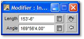
Using the DMS Format:
0~0ʹ0ʺ (the ʹ~ʹ represents the degree symbol)
 Note:
Note:
The letter ‘d’ can be used in place of the ‘~’ symbol
If there are no numbers for seconds, use ‘0’.
5. Drawing in a clockwise direction is usually the way you will need to draw. You may need to try it first to determine the direction you need to go.
6. Place the line on your drawing by clicking the start point and the end point. The ends of this line (Chord) are going to be the start and end points of the arc.
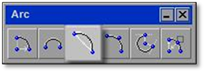
7. Next, open the arc tool in the Draw Toolbox called Insert an arc between two locations defining the chord.
8. Turn off your constraints.
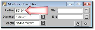
9. In the modifier for the Arc tool, set the radius of the arc as specified by the property survey (R).
10. Using inference, click on one end of the line you placed in step # 6.
11. Using inference, click on the other end of the line. An arc will be drawn with the radius specified.
 Note:
Note:
As with all the arc tools, the radius will be drawn in a counter‐ clockwise direction. In some cases, you may need to start with your second location first.
12. After placing your arcs, you can remove the chord lines.
13. When you are finished placing the property lines on your drawing, be sure to go back to the Data Format option and change the Angle back to Decimal.